CANWeatherBoard2.0
Jump to navigation
Jump to search
Programming CAN Weather Board v2.0 / v2.1[edit | edit source]
Preparation[edit | edit source]
- Required items: Linux Board with CAN bus connection, ST-LINK programmer
Bootloader Programming[edit | edit source]
- The CAN Weather Board uses the same bootloader as the Mini IO board.
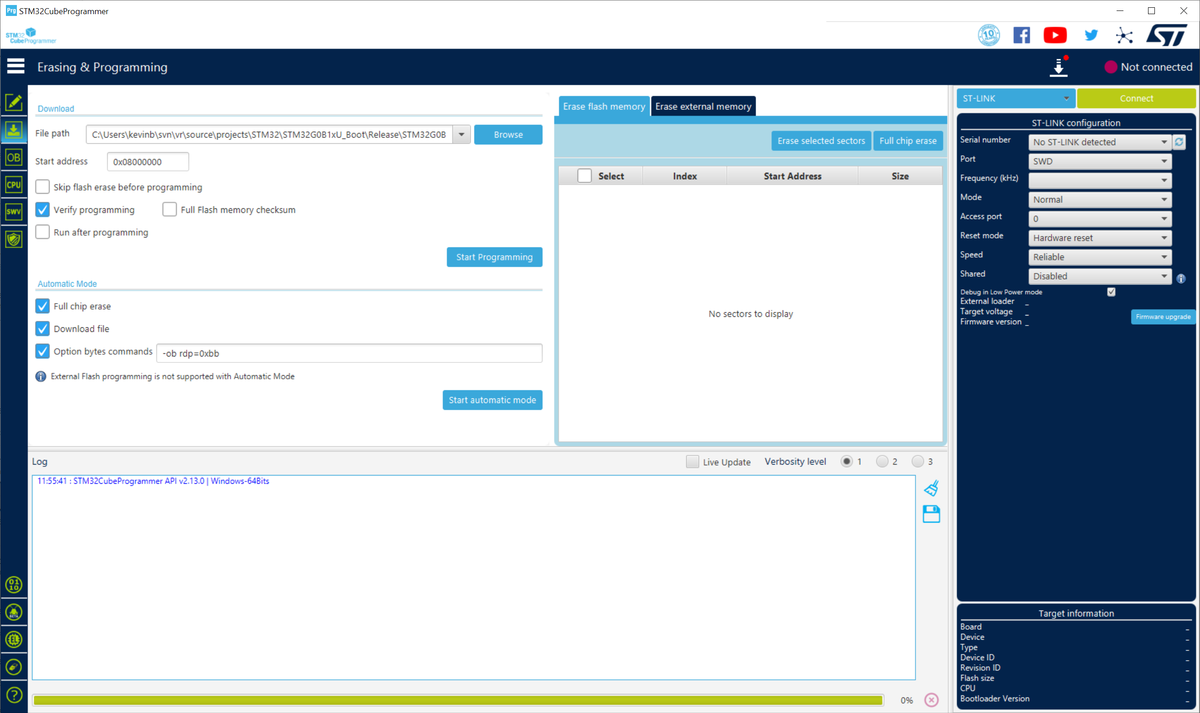
- Open STM32CubeProgrammer program.
- Select 'Programming' section on the left menu.
- Ensure settings are correct, and click the 'Start automatic mode' button.
- File Path for correct Boot Loader
- Start address 0x08000000
- Verify Programming checked
- Full Chip Erase checked
- Download File checked
- Option Bytes commands set to "-ob rdp=0xbb" for Code Readout Protection
- Plug in the STM32 programming cable into the board.
- Power on the board.
- Watch the programming output to see if the board is programmed.

Weather Board Firmware Programming[edit | edit source]
- reset the board by unplugging and replugging in the Power / CAN cable.
- watch the bootloader lights pattern to show fast blinking.
- run the script ./can_wx_program.sh on the board, which runs vr-canboot with the current version of the Weather Board firmware.
- This script looks like this:
#!/bin/bash
echo "please press any key when board is plugged into CAN bus and bootloader is blinking"
read WAIT
vr-canboot --start 0x10000 -f CAN_WX_Board_2.0_v2.0.5.bin -v -a 170
# download the firmware file: wget http://readonly:secret@svn/svn/source/projects/STM32/CAN_WX_Board_2.0/Release/CAN_WX_Board_2.0_v2.0.5.bin
VRSerial Setup[edit | edit source]
- After programming, the board should reboot into the application. The application will connect over CAN and you should see it at address VRSN00000170.
- Set a VRSerial:
VRSN170 SET VRSERIAL 12345
- Set a ComponentID:
VRSN170 SET COMPONENTID 123
- Commit:
VRSN170 COMMIT
- Almost done ... Apply a board serial number to the board, and see next section.
Temperature testing[edit | edit source]
- A separate temperature testing step is needed for this board, to verify that the external temperature probe is working correctly and accurately.
- Please refer to the following image. The LM4040 board red+black power connection is plugged into the 'I2C' port, and the yellow probe wire connects to the input port of the temperature probe, the 'H01' side of the temp probe.
- This should output a temperature of -11.4 ~ -11.5 C when using "GET TEMP2" on the CAN WX board.
